stardustsailor
Well-Known Member
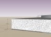
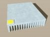
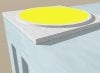
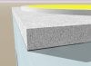
A great thing about COB technology ,is the ability of the array(s) to be directly installed on a heatsink / thermal pad( in case of liquid cooling ).
The elimination of 'Metal Core PrintedCircuitBoard " by itself is the total absence of three layers ..
1) Copper (solder pads/traces ) layer (50-100 micron / 0.05-0.1 mm micron )
2) Thermal conductive / electrical isolating layer (5-50 micron / 0.005-0.05 mm )
3) Aluminium substrate layer (0.5 -2 mm )
Add also
4) Solder layer ( 50-200 micron )
and
5) Thermal interface material between MCPCB and heatsink (50- 200 micron )
5 layers of different "surface grit contact" level
and with different thermal
and mechanical (expansion ) characteristics ...
Are gone for good ...
( For the led DIYer ? That is a touch of Heaven! ... )
... )
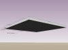
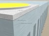
What stands between The CXA array and the heat sink...
Is a thin ( Thin to win ! ) layer of paste or pad ...
And while cooling becomes more efficient ...
And less demanding than of small format leds ...
Still it has to designed and done carefully ...
So,lets cut to the chase...
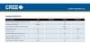
Let's refresh some Cree knowledge acquired ...
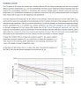
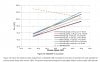
More about Thermal resistance ...
Tj from Tsp / Tc ...
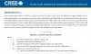
......

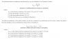
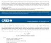
And about TIM thermal resistance calculating ....
The elimination of 'Metal Core PrintedCircuitBoard " by itself is the total absence of three layers ..
1) Copper (solder pads/traces ) layer (50-100 micron / 0.05-0.1 mm micron )
2) Thermal conductive / electrical isolating layer (5-50 micron / 0.005-0.05 mm )
3) Aluminium substrate layer (0.5 -2 mm )
Add also
4) Solder layer ( 50-200 micron )
and
5) Thermal interface material between MCPCB and heatsink (50- 200 micron )
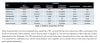
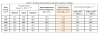
6) Consider also , the extremely low thermal resistance ( 0.8 C / W ) between
semiconductor's junction and bottom of the array case ..
Rθj-c CXA30x0 = ΔΤ { Tj - Tc (aka Tsp ) } / Heat Power = 0.8 C / W ....or K /W ....
5 layers of different "surface grit contact" level
and with different thermal
and mechanical (expansion ) characteristics ...
Are gone for good ...
( For the led DIYer ? That is a touch of Heaven!
... )What stands between The CXA array and the heat sink...
Is a thin ( Thin to win ! ) layer of paste or pad ...
And while cooling becomes more efficient ...
And less demanding than of small format leds ...
Still it has to designed and done carefully ...
So,lets cut to the chase...
Let's refresh some Cree knowledge acquired ...
More about Thermal resistance ...
Tj from Tsp / Tc ...
......
And about TIM thermal resistance calculating ....
Last edited: