Dimming Meanwell B Models with Arduino and X9C104

DeMoNeye

Well-Known Member
Arduino, I know has built in PWM dimming, but you then need to add additional hardware to step up the PWM signal to 10V for Meanwell drivers.

Could I use a X9C104 100K digital pot instead? There's a library available and that little device gives a range of 0 to 100K ohms in 1k steps (taps). I know there are digital pots out there with a larger number of steps (taps) but 100 should be enough.
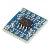
s-l1600.jpg
 

dandyrandy

Well-Known Member
No idea but I'm following. I work in electronics but have never fooled with these. My buddy I work with is 45 and he and an associate have built and sold many 3d printers they sell to various schools as well as one of the nuke sites in Tennessee. He said they have new I/o modules more like a plc controller. He likes my weed. I give him all for free. One of the sharpest electronic techs I have worked with. And I'm an old man. Anyway I was retiring a couple years ago but have delayed it until spring. This is a project that I would like to incorporate with a closed loop system to measure temp of ambient air, heatsink, air flow in my exhaust and control the light intensity as well as airflow on my exhaust. I have a flow sensor I purchased for looking at airflow and controlling the blower with a 0-10 volt reference from the Arduino and the motor drive for the blower. This gives me something to do to avoid the old lady in retirement...
 

DeMoNeye

Well-Known Member
Annoyingly I'm cashless till about mid November... :( First purchase will be an Arduino... If anyone has got one sat doing nothing in a desk drawer, think of me. PM me and I'll cover the postage to send it to me... :)
 

VegasWinner

Well-Known Member
Arduino, I know has built in PWM dimming, but you then need to add additional hardware to step up the PWM signal to 10V for Meanwell drivers.

Could I use a X9C104 100K digital pot instead? There's a library available and that little device gives a range of 0 to 100K ohms in 1k steps (taps). I know there are digital pots out there with a larger number of steps (taps) but 100 should be enough.

View attachment 3804972
What you want is a plc style 5v to 20v owm converter. They average $10 each. Used for industrial controls. Search ebay they are made in China. Peace
 

BobCajun

Well-Known Member
All you need to add to the Arduino is an optocoupler and a resistor. You can get the details with a search. I put one together myself. Pretty easy.
 

wietefras

Well-Known Member
Agreed on the optocoupler solution. I've also used a driver chip to do the 10V PWM

Although I would assume this digital pot should work too.
 

BobCajun

Well-Known Member
Be a lot easier just to use a normal analog pot. If you want accuracy in adjusting it, just put a current meter on it.
 

DeMoNeye

Well-Known Member
Be a lot easier just to use a normal analog pot. If you want accuracy in adjusting it, just put a current meter on it.
Currently have a 100k analog pot wired in - I want a pot that I can change the resistance of programmatically so the microcomputer can control the dimming...
 

BobCajun

Well-Known Member
Currently have a 100k analog pot wired in - I want a pot that I can change the resistance of programmatically so the microcomputer can control the dimming...
Oh okay I see. I've never used a digital one so can't really provide any help there.
 

VegasWinner

Well-Known Member
Currently have a 100k analog pot wired in - I want a pot that I can change the resistance of programmatically so the microcomputer can control the dimming...
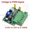
you need one of these perhaps. pwndriver.jpg It also needs a 12v power supply and a pwm driver signal using a 55 timer circuit perhaps. peace
 

DeMoNeye

Well-Known Member
Just bought a 16x2 display/button kit, real time clock, 2 x mains relays and a digital potentiometer.

Bought a small kit of breadboard, wires, resistors, transistors etc. to help with prototyping.

Will report back how much luck I have building. I used to be a programmer using a now dead language called Pick/Databasic for 20 years so I've just to transition to a microcontroller...

Anyone out there with experience of using a Arduino/RaspberryPi and can advice on which OS I should be loading?
 

Gromax 3590B

Active Member
For dimming a HLG Meanwell B model with an arduino all u need is a 2n3904 transistor and a 14300 ohm resistor.

I choose the 2n3904 for the quick switching up to 300MHz.

The arduino has a PWM output of 5V 20mA max. The load that i want to switch (Meanwell HLG driver) has 10V built in so i don't need an additionel power source.

At 10 percent dimming the current between the dim wires is 1mA. 1mA is the maximum current that has to be switched. The base current and the collector current ratio is 1/10 (hfe=10) so i only need 0.1mA base current to drive the transistor in saturation.

To be sure that the transistor goes in saturation i multiple the base current with 3. The base current that i need is 0.3mA

Now i have to calculate a good base resistor with the formula R=U/I. U=5V -0.7V that i lose trough the base/emitter junction. The current i want is 0.3mA.

R=4.3/0.0003 ohm
R=14333.3333 ohm

:eyesmoke:
 
Last edited:
Top