My First DIY LED project cxb3590

SupraSPL

Well-Known Member
I covered my solder points with a hot glue gun, because I was worried too, quick fix ;) .....Im not too sure how to use my multimeter or test the pots. Also would any swtich work? Its really sad how little i know about electronics lol.....this whole thing has kinda made me want to go back to school for it. Any advice on drivers I mentioned for the fans?
To test the pots, you turn the dimmer knob all the way to the right and then check resistance between these 2 pins.
dimmer.png
 

SupraSPL

Well-Known Member
If I run 2 fans on one of those would I be getting similar fan speed as these two at 6.5v 2.5a ?
The fans would be wired in parallel so each fan will run at 12V and draw about .12A. So each fan will dissipate about 1.44W and the total load on your power adapter would be .24A. That is about 25% load on a 1A adapter so you could run ~7 fans on an APV-12-12.

http://www.arctic.ac/us_en/arctic-f14-standard.html
 
Last edited:

silvrsurfer77

Well-Known Member
The fans would be wired in parallel so each fan will run at 12V and draw about .12A. So each fan will dissipate about 1.44W and the total load on your power adapter would be .24A. That is about 25% load on a 1A adapter so you could run 7-8 fans on an APV-12-12.

http://www.arctic.ac/us_en/arctic-f14-standard.html
Im not sure what you mean by 1A adapter? I thought I connected the the APV-12-12 to the ac power source and then the output to the fans in parallel ? I need an adpater between the driver and fans?
 

silvrsurfer77

Well-Known Member
Thanks, I figured to test those two pins, I just didnt know the setting on the multimeter but I just figured it out, sorry still learning
 

silvrsurfer77

Well-Known Member
@SupraSPL For the switch to activate full power and dimming, will a 3 pin 12v rocker switch work ? Like these

And if I want to add a power switch can I use the same kind of switch in the AC version 10A/120v ?
 

SupraSPL

Well-Known Member
Yes that will work for the dimmer, although the LED will not light up.

Looks like that switch may not be rated for 120V. You can use any single pole 120V rated switch on a 120V circuit but if you ever plan on powering it with 240V you would want to use a 250V rated double pole switch like this.
 

silvrsurfer77

Well-Known Member
Thanks, I wish I didnt order them already, Im sure Ill find some use for them lol. I thought the switch for the dimmer was only 12v, I guess the 120v from the wall is the same voltage in the dimming circuit? Im assuming its also AC? the leds wont light up because its only passing 12v thru the switch ? I dont plan on using anything more than the standard 110/120v outlets. Im gonna try and find those in a cylindrical rocker style.....holes are easier than rectangles to cut lol. Thanks again for helping the newbs like me out :)
 

alesh

Well-Known Member
Thanks, I wish I didnt order them already, Im sure Ill find some use for them lol. I thought the switch for the dimmer was only 12v, I guess the 120v from the wall is the same voltage in the dimming circuit? Im assuming its also AC? the leds wont light up because its only passing 12v thru the switch ? I dont plan on using anything more than the standard 110/120v outlets. Im gonna try and find those in a cylindrical rocker style.....holes are easier than rectangles to cut lol. Thanks again for helping the newbs like me out :)
Do I get it right?
schematics.png
Full power when the switch is disconnected, otherwise dimming according to pot? If that's your plan you can use the 12V switches you ordered.
 

silvrsurfer77

Well-Known Member
Yes thats my plan, I will also be ordering some AC dpst switches for power on and off also. So two switches one to turn on and off, and the other full power/dim.
 

silvrsurfer77

Well-Known Member
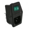
I bought some of these for the power inlet and power switch combo. Anyone mind telling or showing me how to wire it to the driver. Just confused on which prongs are for what on the switch itself. I know to connect the outlet prongs to the switch and then the switch to the driver.
 

Attachments

silvrsurfer77

Well-Known Member
HELP ANYONE

So I have everything 95% done on this fixture and about 3/4 done on my other fixtures, but Im having a slight issue.

Everything works great untill I hook up a 100k pot. Once i solder the two wires to the pot and turn on I get a few flickers here and there. Ive tried 3 pots so far, figured my connections maybe, tried re-soldering them still flickers particularly if i touch the dimming wires at all. I ended up breaking 3 pots already..my guess is from heating to much with soldering iron....once they dont work the flickering stops for the most part. The wire is fine stranded stranded tinned copper silicone shielded.....is it possible the movement of the wire is messing with the resistance or bad connection or bad pots?
 

silvrsurfer77

Well-Known Member
make that 4 pots now.....tried using thinner gauge wire, even checked some youtube tutorials for guitars, the pot I just tried gave me a max reading of 90k and after I soldered it up and tested the resistance from the wires it read 137....also jumps all over the place.....I know I need a new solder tip, doesnt want to hold solder too well, I need flux for everything even tinning a wire....going to get new tip, hopefully thats the cause of all this :(
 
Top