User64
Well-Known Member
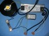
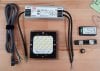
Recently moved and am unpacking all the LED things for a single light setup. I've got the LED, Driver, Meter, Cord, 18 AWG Solid Core Wire, 2 Port WAGOs and the Potentiometer for dimming. Can not for the life of me find the bookmark that explained how to wire them properly. Can anyone explain or point me in the direction to learn the proper way to wire these so they function as intended ?
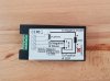
The potentiometer seems pretty straight forward but the meter and shunt are confusing me. The Input seems pretty straight forward with the cord. Green should be Ground, ACL Brown should be Live and ACN Blue should be Neutral. Just need to get the Output figured out, unless I'm completely wrong in the input wiring.
The potentiometer seems pretty straight forward but the meter and shunt are confusing me. The Input seems pretty straight forward with the cord. Green should be Ground, ACL Brown should be Live and ACN Blue should be Neutral. Just need to get the Output figured out, unless I'm completely wrong in the input wiring.